portfolio-v1
Taser ⚡🔧
📌 Overview
I finally got my hand on a 3d printer and i wanted to test my CAD skills, and for some reason my mind told me hey designing a case for a taser would be fun and beneficial. This project tested my skill and also improved my problem solving and creative thinking, especially in the engineering field. It also enchanced my hands-on experience with tools as I had to do a quite a bit of tinkering and soldering.
The taser uses a 3.7V lithium ion battery. It recharges using a tp4056 board, has a safety switch design.
I was able to find out some useful information online about the electrical compoenents of a taser. However I found no luck for the case, so I designed the case completely on my own with nothing in reference to.
Outcome: A fully functional taser that can devliver high voltage.
🛠️ Materials & Components
Electronic
- 3.7V lithium ion battery
- Step up high voltage transfomer
- TP4056 USB C recharging board.
- Wires
- Push button
- On and Off Button
- Green LED
- 100ohm resistor
Mechanical
- PLA case
- M3 Threaded Inserts
- M3 Screws
Tools
- Soldering iron
- Hot glue gun
- Electrical Tape
- Multipurpose wire stripper.
- Scissor
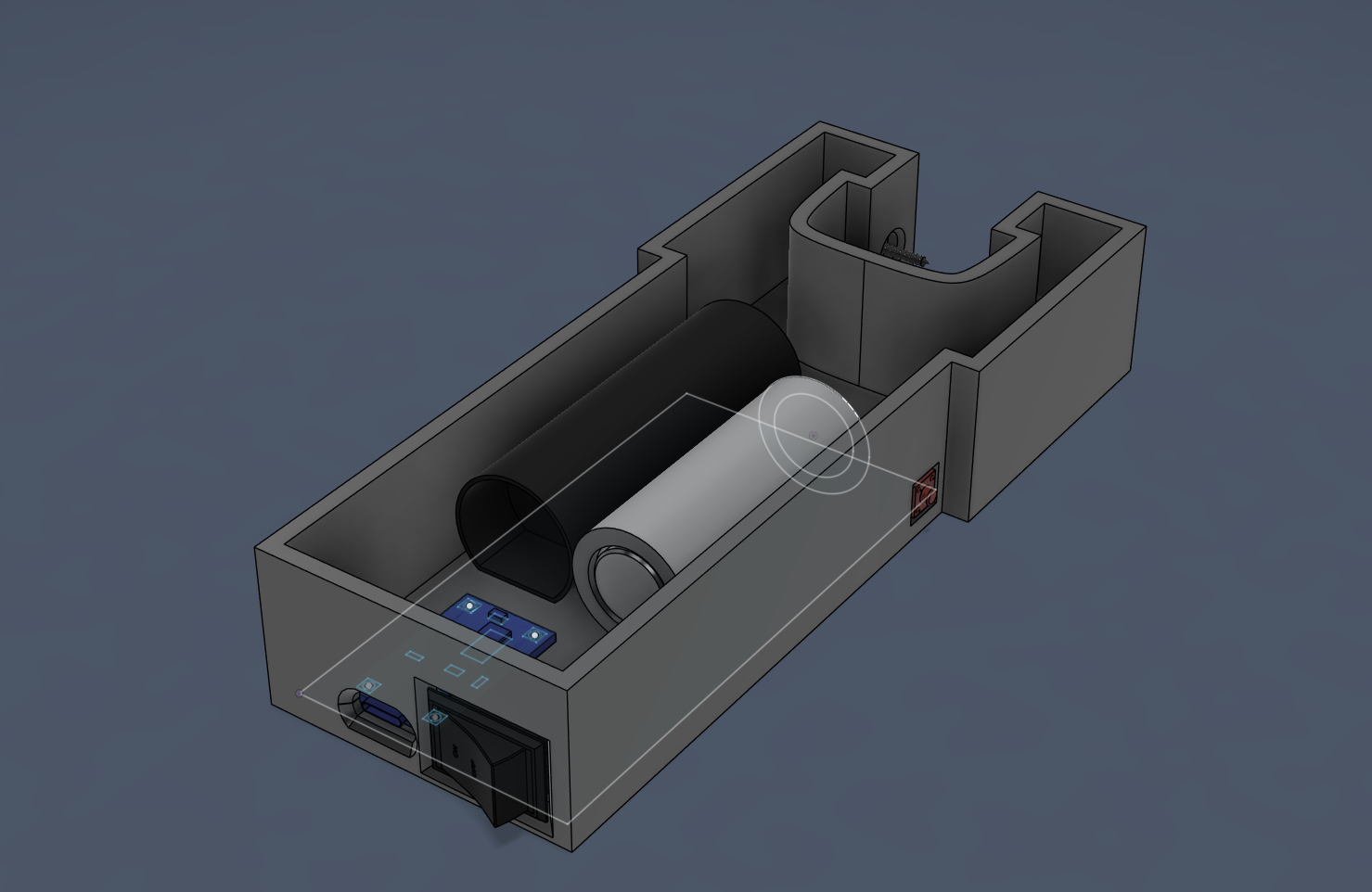
STEP 1 : Model everything
To make sure all the components can fit into the case, I started by individually modelling all the components of the Taser.
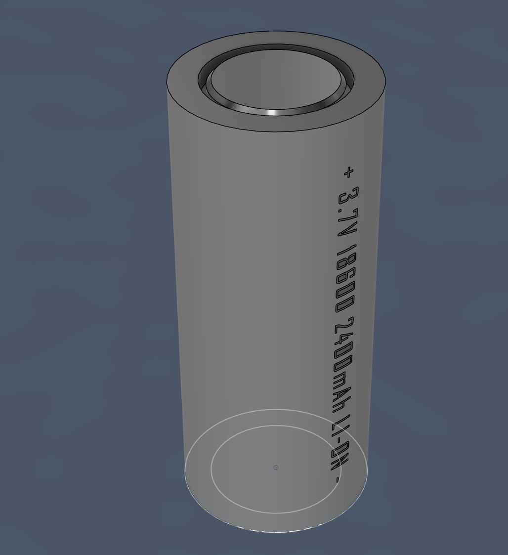
3.7V Battery.
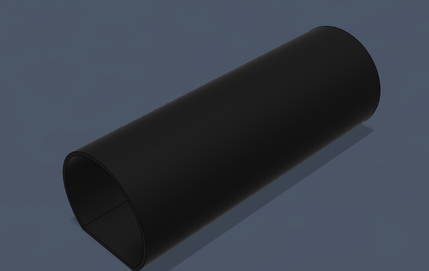
Step up high voltage transformer.
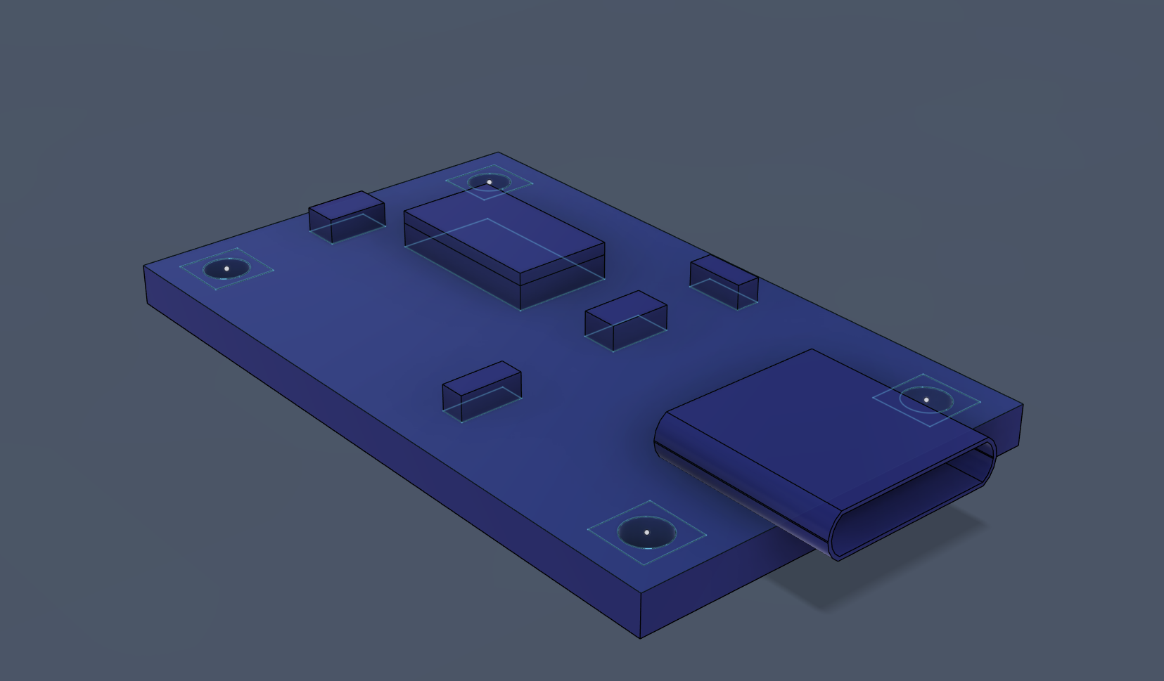
TP4056
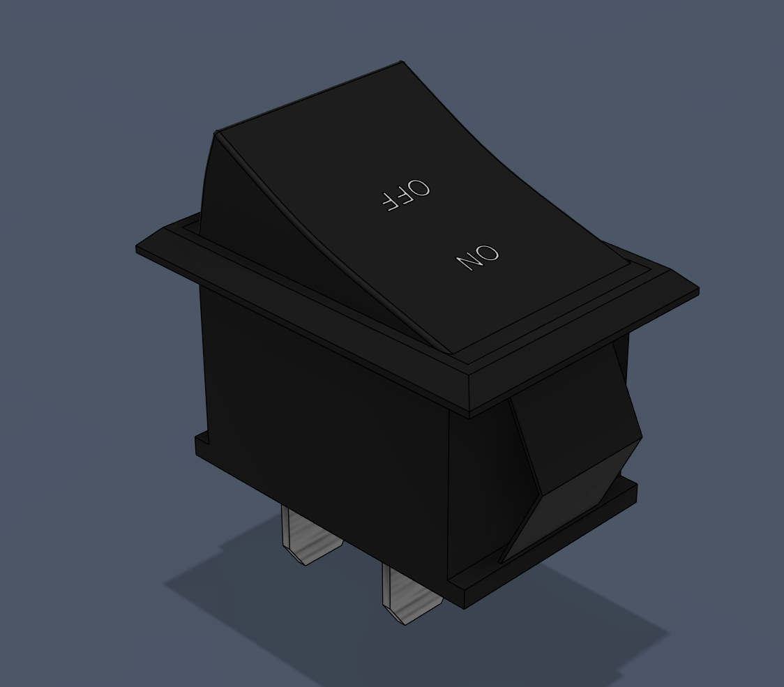
On and Off Switch, I also modelled the push button
In addition I did some brainstorming while waiting for the parts to arrive.
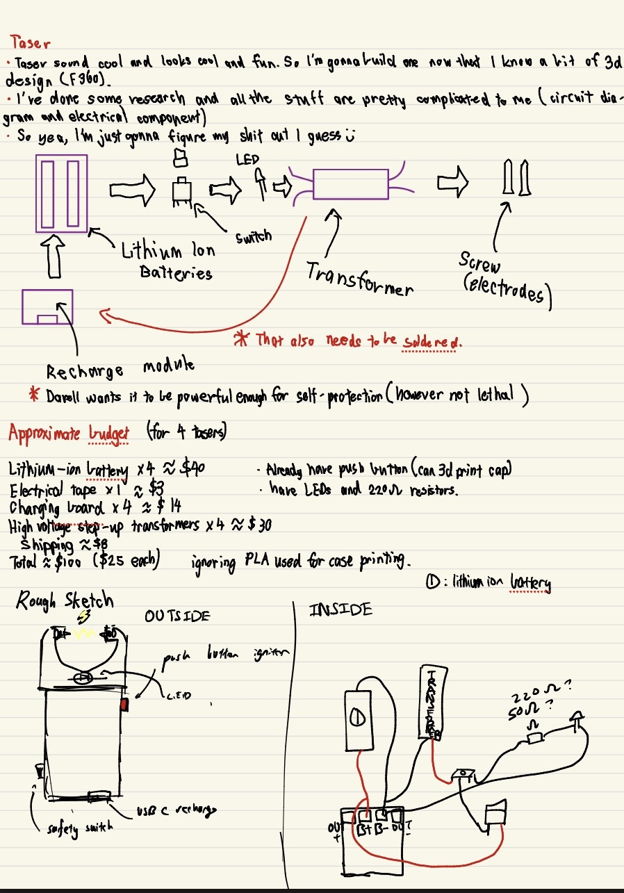
some random brainstorm
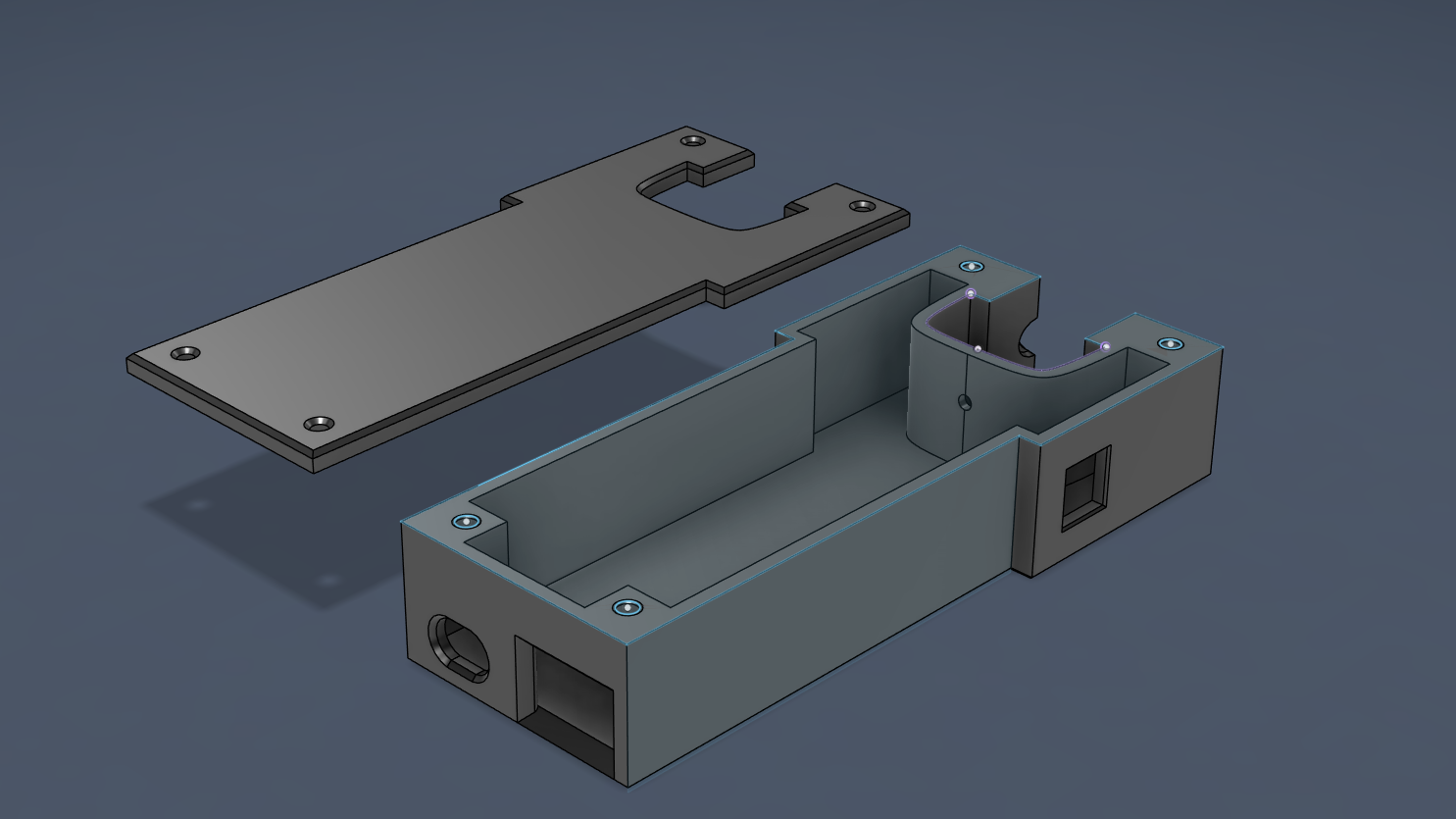
STEP 2: Printing and Testing
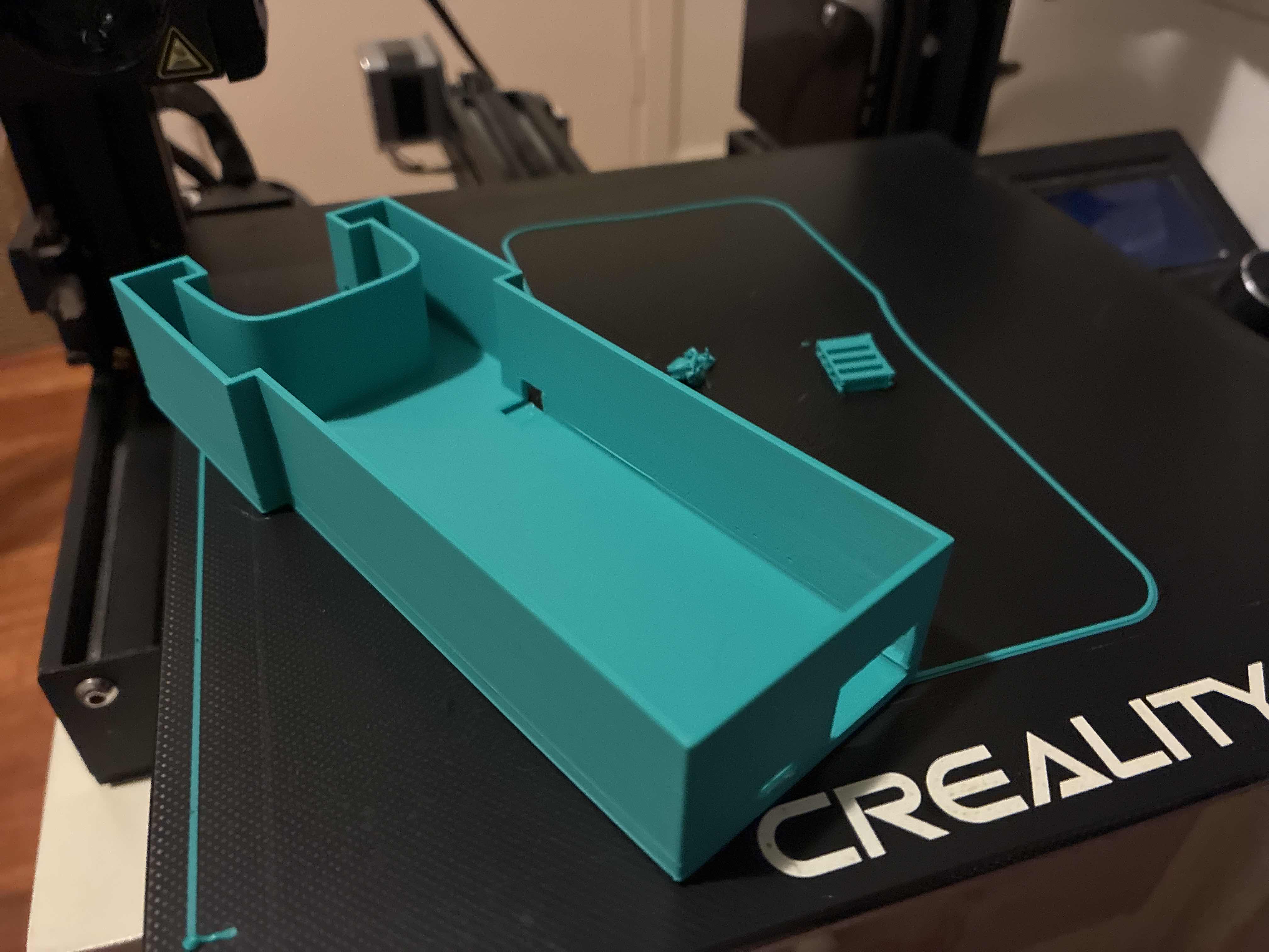
Version 1 of the taser.
Problems of v1
- The hole for on and off switch is not big enough
- The hole for tp4056 is not big enough and is placed slightly too low
- Strength of walls are not good enough, vulnerable to cracks
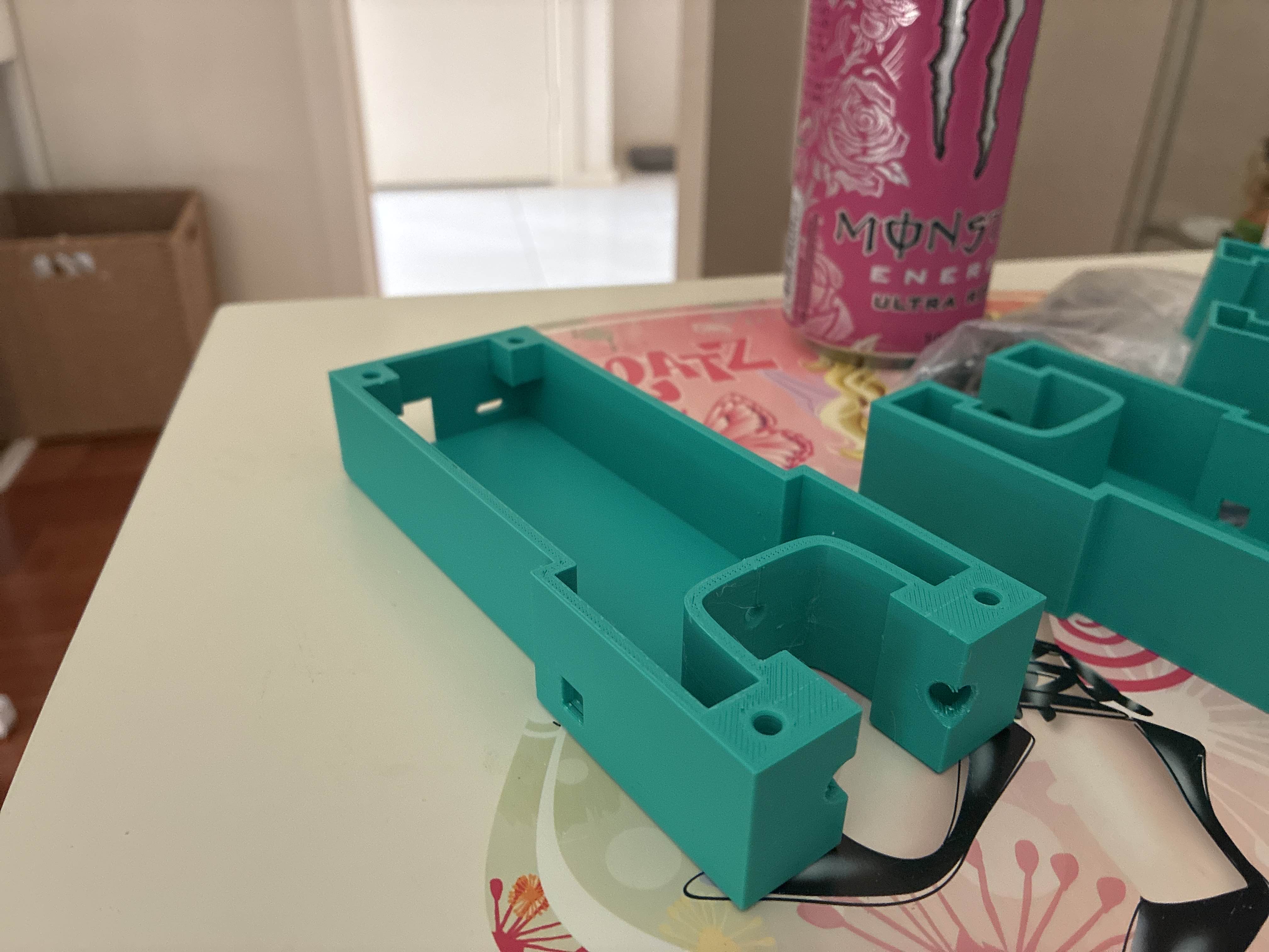
Version 2 of the taser, hole problem improved using offsets and projection, strength fixed by increasing thickness and infill% of print, also made probe circles better.
Problems of v2
- TP4056 is stil kinda awkward, should be placed higher.
- Probe circle size is fine but position is not optiaml, it should be placed in the orners so it looks like a 八 shape.
- push button’s location doesn’t feel ergonomic.
- Still don’t have cover designed
- Haven’t designed threaded insertion holes.
Version 3 of the taser, Probe circles location optimised, infill increase to 50%. Button position is more ergonomic. Threaded insertion designed. Cover designed. LED hole designed.
Problems of v3
- TP4056 is still awkward, although less awkward but still could be better, hole shnould be bigger so when being used you can see the lights on the board.
- The button hole is fine but realised I have bigger better buttons at home, so next version will use that instead.
STEP 3 Actual test of the taser
🧩 Obstacles faced
-Problem: the safety switch feature wouldn’t work.
-Solution:I learned on the spot the that the side you solder the push buttons pins matters a lot. I initially soldered incorrectly which allowed the transfomer to bypass the safety switch. That was solved by soldering correction.
-Problem:The red LED would die because the resistor isn’t strong enough to bring down the power of 3.7V
-Solution:Using my knowledge of activation energy, I don’t have access to a stronger resistor so I swapped red with green, which requires a higher activation energy. This solves the overflow of power.
🎥 Demo Video
STEP 4 FINALE
Still designed the v4 of the taser case, which is the final version.
Version 4, Improved TP4056 hole, Push button hole bigger which suits the bigger better push button that I have.